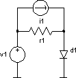
Operating point
 |
noise example |


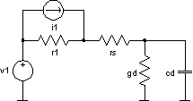
Linearised ac circuit
 |
  
|
Note, that ac magnitude of the input source has to be one.
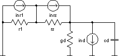
Thermal noise of the resistors
r1 and rs given by:

Shot and flicker noise of the diode d1 given by:

All independent sources eliminated (set to zero), noise generators added
 |
    
|
Noise analysis creates two plots named noise1 and noise2. The first one
contains the information about noise spectral densities, and the second about total
noises. The vectors in noise1 are:
onoise_r1=
onoise_d1_rs =
onoise_d1_id =
onoise_d1_1overf =
onoise_d1 = onoise_d1_rs + onoise_d1_id + onoise_d1_1overf
onoise_spectrum = onoise_r1 + onoise_d1
inoise_spectrum = onoise_spectrum / |A|2
The vectors in noise2 are:
onoise_total_r1 = |
 |
onoise_total_d1_rs = |
 |
onoise_total_d1_id = |
 |
onoise_total_d1_1overf = |
 |
onoise_total_d1 =onoise_total_d1_rs + onoise_total_d1_id + onoise_total_d1_1overf
onoise_total = onoise_total_r1 + onoise_total_d1
inoise_total_r1 = |
 |
inoise_total_d1_rs = |
 |
inoise_total_d1_id = |
 |
inoise_total_d1_1overf = |
 |
inoise_total_d1 =inoise_total_d1_rs + inoise_total_d1_id + inoise_total_d1_1overf
inoise_total = inoise_total_r1 + inoise_total_d1